- 您现在的位置:买卖IC网 > Sheet目录346 > NSVD4001DR2G (ON Semiconductor)IC LED DRIVER LINEAR 8-SOIC
NUD4001, NSVD4001
APPLICATION INFORMATION
Design Guide
NUD4001
1. Define LED’s current:
a. I LED = 350 mA
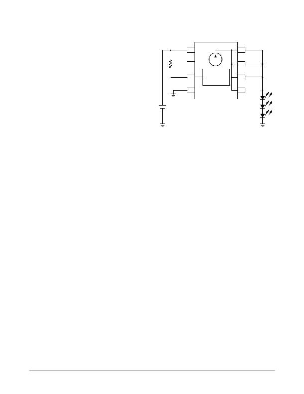
V in
Boost
1
2
8
7
I out
I out
2. Calculate Resistor Value for R ext :
a. R ext = V sense (see Figure 2) / I LED
b. R ext = 0.7 (T J = 25 ° C)/ 0.350 = 2.0 W
3. Define V in :
a. Per example in Figure 6, V in = 12 V
R ext
GND
3
4
Current
Set Point
6
5
I out
I out
4. Define V LED @ I LED per LED supplier ’s data
sheet:
a. Per example in Figure 6,
V LED = 3.5 V + 3.5 V + 3.5 V = 10.5 V
12 V
Figure 6. 12 V Application
(Series LED’s Array)
5. Calculate V drop across the NUD4001 device:
a. V drop = V in – V sense – V LED
b. V drop = 12 V – 0.7 V (T J = 25 ° C) – 10.5 V
c. V drop = 0.8 V
6. Calculate Power Dissipation on the NUD4001
device’s driver:
a. P D_driver = V drop * I out
b. P D_driver = 0.8 V x 0.350 A
c. P D_driver = 0.280 Watts
7. Establish Power Dissipation on the NUD4001
device’s control circuit per Figure 4:
a. P D_control = Figure 4, for 12 V input voltage
b. P D_control = 0.055 W
8. Calculate Total Power Dissipation on the device:
a. P D_total = P D_driver + P D_control
b. P D_total = 0.280 W + 0.055 W = 0.335 W
9. If P D_total > 1.13 W (or derated value per
Figure 3), then select the most appropriate
recourse and repeat steps 1 through 8:
a. Reduce V in
b. Reconfigure LED array to reduce V drop
c. Reduce I out by increasing R ext
d. Use external resistors or parallel device’s
configuration (see application note AND8156)
10. Calculate the junction temperaure using the
thermal information on Page 7 and refer to Figure
5 to check the output current drop due to the
calculated junction temperature. If desired,
compensate it by adjusting the value of R ext .
http://onsemi.com
4
发布紧急采购,3分钟左右您将得到回复。
相关PDF资料
NV890101MWTXGEVB
BOARD EVAL NV890101MWTX
NV890201MWTXGEVB
BOARD EVAL NV890201MWTX
ODC5ML
OUTPUT MODULE DC STD 18MA 5VDC
ODC5ML
OUTPUT MODULE DC STD 18MA 5VDC
ODC5Q.11
OUTPUT MODULE DC QUAD 18MA 5VDC
ODC5Q
OUTPUT MODULE DC QUAD 18MA 5VDC
ODCM-15
OUTPUT MODULE DC 16MA 15VDC
OR4E6-FPGA-EV
BOARD EVAL FOR ORCA OR4E6 FPGA
相关代理商/技术参数
NSVDTA143ZET1G
制造商:ON Semiconductor 功能描述:SS SC75 BR XSTR PNP 50V - Tape and Reel
NSVDTC114YM3T5G
制造商:ON Semiconductor 功能描述:SS SOT723 BIAS RES XSTR - Tape and Reel
NSVDTC143ZET1G
制造商:ON Semiconductor 功能描述:SS SC75 BR XSTR NPN 50V - Tape and Reel
NSVDTC144WET1G
制造商:ON Semiconductor 功能描述:SS SC75 BR XSTR NPN 50V - Tape and Reel
NSVED06I1632BL
制造商:Panduit Corp 功能描述:VERTICAL EXHAUST DUCT (VED) FO 制造商:Panduit Corp 功能描述:VERTICAL EXHAUST DUCT (VED) FOR NET-SERV - Bulk
NSVED06I1632WH
制造商:Panduit Corp 功能描述:VERTICAL EXHAUST DUCT (VED) FO 制造商:Panduit Corp 功能描述:VERTICAL EXHAUST DUCT (VED) FOR NET-SERV - Bulk
NSVED06I3266BL
制造商:Panduit Corp 功能描述:VERTICAL EXHAUST DUCT (VED) FO 制造商:Panduit Corp 功能描述:VERTICAL EXHAUST DUCT (VED) FOR NET-SERV - Bulk
NSVED06I3266WH
制造商:Panduit Corp 功能描述:VERTICAL EXHAUST DUCT (VED) FO 制造商:Panduit Corp 功能描述:VERTICAL EXHAUST DUCT (VED) FOR NET-SERV - Bulk
